STP is enabled by default on Cisco switches and it is used to add redundant links into a network while avoiding loops.
So in the event that a network link fails a LAN will keep working. Ideally no single point of failure will bring down the LAN. It’s also key that all devices on a VLAN can reach each other, so STP can’t block too many ports.
Loops are prevented by STP enforcing an additional check on a switches interface: If it’s in “STP Forwarding” state (in that VLAN only) then it works as normal. If the interface is in the “STP Blocking” state it blocks all user traffic on that interface (again in that VLAN only).
When STP is disabled you can get loops in your network.
There are three main issues that this causes:
- Broadcast Storms: A packet with a destination that isn’t known to a switch arrives (or a braodcast package), and there is no accessible device on the network with that address.
The packet is sent out to on all ports other than the one it was received on as would be expected. When a network is looped this packet will eventually find its way back to this switch and the process will repeat. This can bring down a network very quickly and will continue until stopped manually. - MAC Table Instability: A switches MAC address table is repeatedly updated with incorrect entries during a broadcast storm. This results in frames being sent to the wrong locations.
- Multiple Frame Transmission: While a loop is happening frames can get repeatedly retransmitted to their intended host, which can cause application failure.
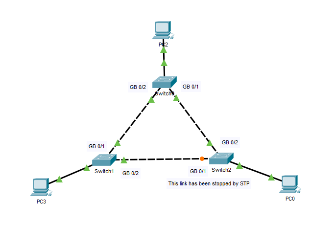
In the diagram below we can see STP, as is automatically configured on a Cisco switch working correctly.
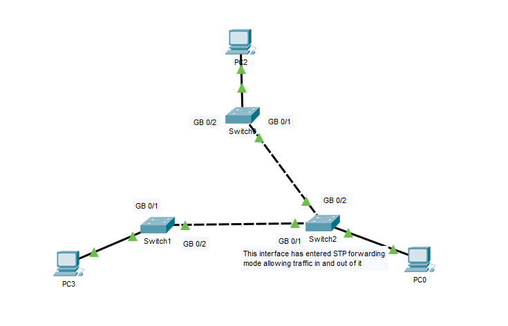
Below we can see what happens when the link between Switch 0 and Switch 1 goes down:
STP decides which ports to put into the forwarding state using the Spanning Tree Algorithm. Any not selected to be in the forwarding state are automatically put into the blocking state.
How a switch finds the best path to a root switch:
- The STP selects one switch as a root switch. On this switch all working interfaces are placed into the forwarding state (and are made Designated Ports).
- On each switch, other than the root switch, the interface with the lowest administrative distance (lowest root cost) is declared as the root port and put in a forwarding state. If the cost is tied then it will go with the route that has the lowest bridge ID (combination of bridge ID and bridge MAC address).
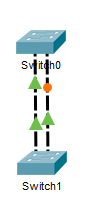
- If there is a switch that has two connections to another switch (as shown in the image below) then the one connected on the lower port number is made the root port.
1.3.a STP mode (PVST+ and RPVST+)
Spanning Tree Protocol:
Common Spanning Tree (CST or STP – 802./D)
Most common flavour of spanning tree protocol. Enabled by default and can work with most other makes of switch straight out the box. In the event that a link failure occurs the average convergence time is 30-50 seconds before everything is restored.
Takes 15 seconds in the listening mode
Another 15 seconds in the learning mode
Per-VLAN Spanning Tree (PVST+) (ieee)
This is a Cisco proprietary protocol. Using this protocol Cisco switches can assign different root bridges for different VLANS.
So different links will be blocked depending on the VLAN the traffic is tagged with, so in theory this helps reduce the impact of lines getting too congested, and keeps the network runni ng more smoothly while still avoiding loops.
When using PVST the default priority isn’t the default of 32768, it adds on the ‘system ID extension – which is the VLAN number’
Rapid Spanning Tree (RSTP – 802./w)
Under Rapid Spanning tree the convergence time is reduced to closer to 2 seconds. The switch jumps into action as soon as it detects its link to the root go down, and then lets the other switches know what’s changed.
RSTP is ‘backwards compatible’. So if there is a switch on the network running standard STP it wont break the network, but RSTP will revert back to STP until all the switches on a network have RSTP enabled.
Per-VLAN Rapid Spanning Tree (PVRST) (Or RPVST+ is rapid per-VLAN Spanning Tree)
Like PVST this is a cisco proprietary protocol. It works in the same way as RSTP but on a per VLAN basis.
Enabled by the commands:
enable
configure terminal
spanning-tree mode rapid-pvst
Multiple Spanning Tree Protocol (MSTP – 802./S)
This is the industries answer to the Cisco specific protocol. It does the same thing as the per-VLAN Rapid Spanning Tree but made it non-proprietary. It’s more complex than RPVST and isn’t that widely used at the moment. It’s not currently in the CCNA syllabus but it’s nice to know.
1.3.b STP root bridge selection
The Root Switch is the most important switch on the network. The switch that is declared the root is the one all the other switches try to find the best route to, and then block all the other redundant connections (Until that route is broken, then they find another route there).
How do you select the correct switch to be the root bridge? When looking at the three tier system you don’t make an access layer switch the root bridge. If your core switch is a layer three switch you don’t make that your root switch either, it’ll be one of the switches on the distribution layer. (You should also assign another switch on that level to be the backup root switch)
ELECTING THE ROOT BRIDGE
Each switch claims to be the root. The best switch is selected based on which one has the lowest bridge priority – will be between 0 and 65535 and is manually assigned). (By default the bridge priority is set to 32768 and can be changed in increments of 4096.)
The bridge priority is then combined with the MAC address to create the Bridge ID (BID).
If the bridge priority is the same on multiple switches the one with the lowest switch MAC address is declared the root switch. (we don’t really want this as older switches tend to have lower mac addresses).
(If there are multiple connections to the same switch for redundancy then the one with the lowest port number is selected as the best route).
Example output:
enable
show spanning tree
VLAN0001
Spanning tree enabled protocol ieee
Root ID Priority 32769
Address 0001.C786.6C97
Cost 19
Port 1(FastEthernet0/1)
Hello Time 2 sec Max Age 20 sec Forward Delay 15 secBridge ID Priority 32769 (priority 32768 sys-id-ext 1)
Address 0001.C79E.3B95
Hello Time 2 sec Max Age 20 sec Forward Delay 15 sec
Aging Time 20Interface Role Sts Cost Prio.Nbr Type
————— ——————- ————- ——-
Fa0/1 Root FWD 19 128.1 P2p
How to change a devices Bridge Priority:
enable
configure terminal
spanning-tree vlan 1 priority *an increment of 4096 between 0 and 61440)