OSFP
OSPF (Open shortest path first) is an open source protocol.
It’s an RFC Standard – so every network device should support it.
It’s the only widely used Link-State routing routing protocol, and maintains a LSDB (link-state database). It also doesn’t use TCP, or UDP, it is its own protocol.
OSFPv2 is designed for IPv4, not IPv6. IPv6 will be covered in detail in the next slide page.
Runs the Dijkstra SPF Algorithm (as do all Link-State protocols)
It works for both single area networks and multi area networks as well.
In Single area networks all routers will have to have the exact same topology table, and as a network scales upwards more and more resources are needed to maintain the table.
Multi area networks are used when a network get’s too large and churns through too much processing power so it’s split into several smaller link-state databases. To start with all of the multiple areas need to be connected to “Area 0” – A backbone.
Each of the other areas (e.g. area 1) are seperated from area 0 by an Area Border Router that implements summary routes (all of the routes in the area put together) and pushes that out to area 0. From this area 1 will not need to be linked directly to any area other than area 0.
Autonomous System Boundary Router (ASBR) – This is how you break out of the OSPF network into a network you don’t manage (for example: The Internet). In addition to Area Border Routers – ASBR’s can also do route summarisation.
OSPF Neighbour Relationships
Before OSPF networks exchange routes they have to form a relationship (unlike protocols such as RIP that just send out multi/broadcast packages – so don’t get a response). Once they have established this relationship they only need to send HELLO messages to one another to stay up – and as such they can detect when their neighbour goes down much more quickly than some other routing protocols – speed is an advantage.
The vast majoruty of OSPF troubleshooting happens in the Neighbour Relationship config. It’s important.
The first thing you need to know when setting up OSPF is your own Routers name – its Router ID – (which will be look like the IP address of the highest active interface [and loopbacks always are considered higher than physical interfaces in this process)) that OSPF picks for it.
You can also hardcode the Router ID (which is a good idea – you don’t really want the Router ID changing).
Once you’ve set up a router with the initial network so there is at least one interface that’s up – you can enable OSPF and set the Router-ID yourself (as shown below – worth noting THIS HAS TO BE UNIQUE ON THE SYSTEM) – this then will not change until the Router is rebooted or the OSPF process is reset (this can be done by running clear ip ospf process)
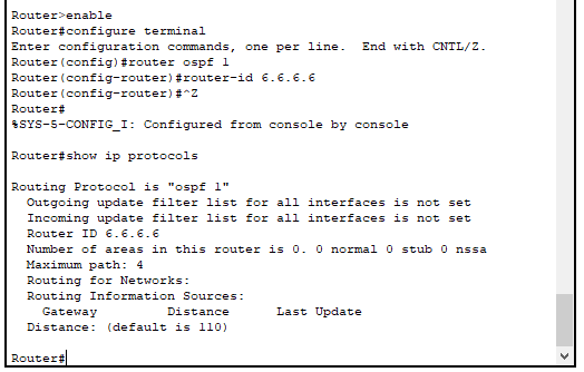
enable
configure terminal
ospf 1
router-id 6.6.6.6
#confirm that it’s worked by backing out into priv mode and running:
show ip protocols
The second step that needs to be taken is the Link-state database needs to be created and populated.
The third step involves actually forming the relationships with other Routers by sending a Hello message out the interfaces. They contain the following information (the ones in bold have to match what the other router has or the other router will not become a neighbour – if the neighbour isn’ t forming it’s probably one of these fields that is wrong):
| 1 – Router-ID | 5 – Neighbours |
| 2 – Hello and Dead Timers | 6 – Router Priority |
| 3 – Network Mask | 7 – DR/BDR IP Address |
| 4 – Area ID | 8 – Authentication Password |
By default the HELLO message will be sent out every 10 seconds on ptp and Broadcast networks and every 30 seconds on NBMA (Non Broadcast MultiAccess) networks. – but this can be changed to anything you want. – but they have to match on both routers.
Receiving a HELLO is the next step in the neighbour relationship formation process. The router checks the message it has received and makes sure that the bold settings the table above match what it has set for it. If any of those settings do not match the HELLO message will be dropped.
Assuming it doesn’t drop the HELLO the router sends a HELLO reply message. This checks to see if the device that sent the HELLO is already in its list of neighbours. If it is not in its list of neighbours then it will add that router to its list of neighbours, if it is already in its list of neighbours then it will reset the dead timer on that neighbour and the process ends.
If it IS a new neighbour then the next step is determining the Master – Slave relationship. This is quite straight forward and just determines which of the two devices talks first.
It’s determined by the “priority” but as this is the same on all routers by default the tie is broken by the Router ID (the higher ID is the master and speaks first).
The master sends across a DBD (DataBase Description) packet – which is basically a summary version of their Link-state database (but not the whole link-state database).
The slave then replies with its own DBD and both of the routers analyse the DBD packet that they’ve received.
Any routes the router (router 1) already knows are safely ignored, but if the DBD received contains a route to a network that the router doesn’t know it will send the other router (router 2) a Link State Request (LSR) about that route. Router 2 will then reply with a Link State Update (LSU) containing all the detail it has on that route (in the form of an LSA – Link-State Advertisment) that isn’t included in the DBD packet.
Note: After each packet is sent (with the exception of the HELLO message) the router receiving the packet will send a Link State Acknowledgement (LSack) to confirm it recieved the packet.
The master and the slave go back and forward with eachother asking questions about the DBD they received until they both have all the information that they need, and once they match the neighbours have synchronised and enter a full neighbour state.
Finally they run the Dijkstra SPF Algorithm to generate the routing table.
Summary of the process:
- Router-ID selected
- Add Interfaces to Link-State Database
- Send HELLO messages on interfaces
- Receive HELLO messages
- Send HELLO reply
- Determine Master-Slave relationship
- DBD analysed and reviewed
- Dijkstra SPF Algorithm run to genereate routing table
- Now they are full neighbours they just send hello packets back and forth
How OSPF handles update: The Role of the OSPF Designated Router, and Backup Designated Router
So what happens when a network (network A) goes down? The connected Router (Rotuer 1) sends an update message to its neighbour (Router 2) telling it that network A has gone down. Router 2 then looks at its Link-state database and (if Rotuer 1 was the only link to network A) it will remove network A from its database and send that update to all of its full neighbours, which will do the same. This can get noisy, if every router is updating all of its direct neighours.
This is where the Designated Router comes into play. The Designated Router is the Router that all the other Routers in an Ethernet segment send their updates to, and then that designated router distrubutes them to all the other routers.
(Note – a designated Router can be a designated router for all of its Ethernet segments, or just one connected Ethernet segment, it’s assigned on a per interface basis)
So using the above example – when network A goes down, instead of updating every neighbour: Router 1 would only update the Designated Router (Using Multicast 224.0.0.6 that just the DR and BDR tune into). The DR would then tell all of its neighbours (On Multicast 224.0.0.5 – The multicast that all OSPF routers tune into), who know not to update all of their neighbours if they are in the same network segment.
Backup Designated Router – If the Designated Router fails you can also have a backup designated router that can automatically take over the role. – So all of the Routers in that network segment will also form full relationships with the Backup Designated Router.
How a Designated Router is elected
The default priority of OSPF Routers is 1, so without intervention all of the OSPF Routers connected to the same internet segment tie for priority – so it relies on whichever device has the highest Router ID.
You would probably want to choose which Router is the Designated Router. Any Router interfaces that you don’t want to be considered as Designated Routers can have their OSPF priority set to 0 (ip ospf 0). The interface with the highest OSPF priority set in an Ethernet Segment will be the Designated Router
On single point to point links you do not need a designated Router. – They’re only needed when there are multiple routers in a segment.
Similarly in segments in which a designated router (and BDR) has been elected, all the other Routers will only form full neighbour relationships with the DR and BDR and none of the other routers on a network.
All of the other Routers become ‘Two way neighbours‘ in which they begin the Neighbour forming process but stop before they exchange Routes.
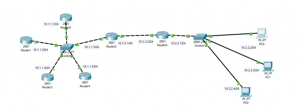
Actual OSPF Setup
Below is the diagram for the network that we will be applying OSPF to. Currently all of the devices in the network diagram have a basic setup – they have been connected as shown and given an IP address and subnet mask. As you would expect they can ping other routers in their network segment but are unable to communicate with Routers in other segments.
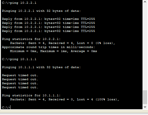
And below is the result of PC0 first attempting to ping its default gateway Router 5 (10.2.2.1) and then trying to get out to Router 0 and being unable to do so.
First thing to do is check to make sure there aren’t already any Routing protocols are already in use. This is done with the command show ip protocols and is run from privileged mode.
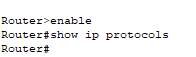
When there are no routing protocols running this will be blank.
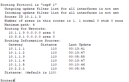
When OSPF has been enabled and configured there will be a lot more detail when this command is run, as is shown below (output from router 2):
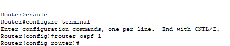
Once you have confirmed the Router doesn’t already have a Routing protocal enabled you can begin configuration.
Start by entering into configuration mode, and running the command router ospf [PROCESS ID]. The process ID is trivial and doesn’t matter, it’s just so we can identify it later if we need to. We will make it 1, and there’s no reason you can’t always make it 1.
Tip – you can have multiple OSPF protocols running on a router at the same time but you do not want to.
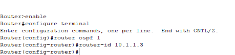
Next up is to give the router a router_id. This can be any ipv4 address. It does not have to be one that is in your network or assigned to one of the routers interfaces. In this case on Router 2 we are going to give it the router id of 10.1.1.3.
The next commmand that needs to be used is the network command. The network command does two things, the first thing it does is specify which networks you want to advertise out (network 10.2.2.0/24). It also then sends HELLO messages out the interface connected to 10.2.2.0 to try and form relationships there. This can be adjusted so that it only does one of those things.
As OSPF is a classless protocol you do need to specify the mask – this is done using a wildcard mask (basically a subnet mask backwards. so on a /24 network the wildcard mask would be 0.255.255.255).
The final part of the command is the network area. In this case we are going to be using area 0 for all of them.
If you want to be lazy and immediately get OSPF running on every interface no matter the network you could use: network 0.0.0.0 255.255.255.255 area 0 – but don’t it’s a security issue. You should go as specific as possible (to the level of the specific IP of an interface) as is shown below.

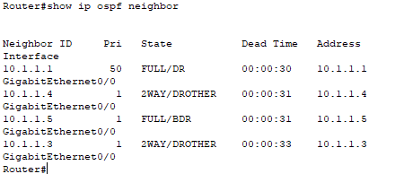
And that’s all there is to the basic config. Once this has been replicated across the network ospf will be working. This can be confirmed with the command: show ip ospf neighbor. (Output from Router 0)
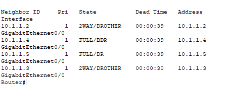
As you can see, in the network segment that contains the 10.1.1.0/24 range the Router with the ID 10.1.1.5 is the Dedicated Router because it has the highest Router ID.
Just for the sake of this exercise we are going to set Router0 to be the Dedicated Router for the 10.1.1.0/24 network segment. The best way to do this is using the priority option.
So first navigate into the interface for 10.1.1.1 (in this case G0/0)

This alone isn’t enough to make Router 0 the dedicated Router though. We also need to run the clear ip ospf process command too on the DR and the BDR. Once we’ve done that we can re-run the neighbour command on any router in the segment to confirm that it is the new DR.
There is another issue here, and that is that if Router 0 goes down, another router will take its place, and not necessarily the one we want to. To stop Routers that we do not want getting elected from bcoming the DR or BDR we can set their priority to 0. This excludes them from the election.
When deciding which router to make the designated router it doesn’t always matter, but generally if you have a hub and spoke topology it’s good practice to make the central hub the designated Router.
Debug mode
When neighbour relationships aren’t forming it can be incredibly frustrating. – but there is a debug mode to help with it. When this happens you can run the command (from priv mode) debug ip ospf adj and then run clear ip ospf process. The whole neighbouring process will repeat and print all of the details to the console. This will also trigger the election of a new dedicated and backup dedicated router if run on those devices.
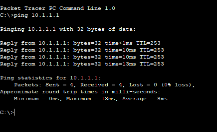
And to show that this is now working, whereas before pings from PC0 would not reach Router 0 we can see that the pings are now getting through.
Metric Adjustment
The metric is how a routing protocol chooses the best route to take to a destination network address. Rip for example uses hop count as a metric. OSPF uses a different metric called ‘cost’. The Formula for cost is as follows: COST = 100 / Bandwidth (in mbps – final result will be an integer, no lower than 1.) and then the cost of each hop is added together to the route and the lowest cost becomes the preferred route.
There is a problem with this Formula. When it was created in the 80’s the bandwidth of networks was nothing like it is today. So anything of 100mbs or higher is automatically given the metric of 1.
If the cost algorithm is going to work properly – this needs to be changed (to the same thing) on every Router in the OSPF network. We can do this by changing the numerator in that equation: so the number bandwidth is divided by. This is achieved by going into router ospf config mode and typing the command: auto-cost reference-bandwidth [new number]
So in this case we are going to make it capable of working out the cost on 10 gig links – so we are going to change the reference bandwidth number to 10,000.
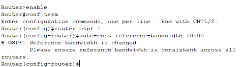
And we can see what that looks like above, along with another reminder to make sure the calculation is the same across all routers.
How to avoid making neighbour relationships with specific LANs.
The main reason you’d like to do this is for security. A bad actor could listen out for HELLO messages, sniff the packets to establish what the different attributes should be, replicate them and then they have a complete list of all your Routes, and can start to poison your network. – set up a mitm attack.
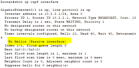
The simplest way to do this is to set an interface to passive. Looking back at our diagram, we are going to do this to the Gb0/1 side of Router5 below.
This will still advertise the LAN out to everybody else but will not send HELLO messages out of it. This can then be confirmed with the show ip ospf interface command from priv mode.
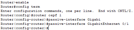
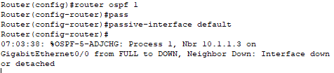
There is also a Cisco preferred way of achieving the same thing that is more secure. This time you run the command: passive-interface default – which puts all of the interfaces into passive mode and loses the neighbour relationships that it already has.
Then you go in and enable OSPF to not be in passive mode for specific interfaces. As shown below for Router 5:
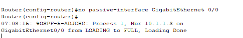
After a few seconds you’ll see that interface, and only that interface start making neighbour relationships again. This is good to know no matter which Routing protocol you are working with – they all use passive interface.
Adjusting the hello timer
The main reason you might want to adjust your hello timer on an OSPF network is to recover from failures faster. By default the OSPF timers fo point to point connectionsare as follows:
Hello – 10 seconds
Dead – 40 seconds
Retransmit – 5 seconds.
When the hello interval is changed it automatically adjusts the Dead timer to be the same ratio.
This is changed first by going into the interface (in this case Router0’s Ge0/0 interface). Then the command ip ospf hello-interval [number of seconds you want to set that interval to]. We will set it to 1 second.
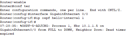
This made Router 0 lose its neighbour relationships. This is because the Hello interval is one of the attirbutes that needs to match on all interface in the Ethernet Segment for the neighbour relationship to be made.
Debugging Process
debug ip ospf [adj] – once this has been enabled you’ll see all of the OSPF messages come through in realtime. Sometimes some clues come through here. Often paired with clear ip ospf process to see the whole process come up.
Show IP route – see if there are the OSPF routes you’d expect there to be. If some are missing it might give you an idea of where to look, if all OSPF routes are missing you can be fairly sure the problem is with the OSPF configuration.
Show ip ospf neighbor – List any ospf neighbours, if this is empty then you can be confident the issue is with forming the neighbor connections.
Show ip protocol – Run this command to see if OSPF is even running. Here we can see when the last update for Routing information sources – you might see that it has been a long time since the last update from a particular device – which could point you in the right direction.
show ip interface – This command shows you what your current ospf setup is on your Router, including all of the timers.
Multi-Area OSPF
In all the previous configuration we have been dealing with OSPF in a single area – Area 0. As OSPF networks scale up the number of Routers in area 0 can impact performance, so multi-area ospf can help with this problem. It does this through summarisation – which isn’t REALLY on the syllabus – but it needs to be understood.
All of the routes in an area are summarised into one (or several) big routes, but not the whole routing table of a Router in the area, given to an Area Border Router, which then advertises to all of the Routers in its connected area that it has access to that route, without all of the more specific routes being needed, and when updates to the OSPF map in area 0 changes the routers in area 1 don’t have to know about it.
Multi-area things to remember:
- All Areas must connect to Area 0 – this is the hub, the backbone of the system. – This can also be done through Virtual Links if there isn’t a direct connection available to Area 0.
- All Routers in an area share the same OSPF map.
- The purpose of Multi-area OSPF is to localise all OSPF updates to an area.
- Requires a heirarchical design. E.g. All routers in an area in a specific netmask, that doesn’t overlap with other areas netmasks.
Autonomous System Boundary Router (ASBR) – This Router is what connects an OSPF network to an outside network (for instance the Internet) which is the only other device that will summarise routes.
Multi Area OSPF Config
Setting up OSPF multi-area is very straight forward, all you need to do is configure an area border router. This is done with the commands below:
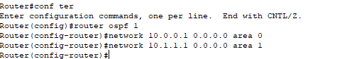
configure terminal
router ospf 1
network 10.0.0.1 0.0.0.0 area 0
network 10.1.1.1 0.0.0.0 area 1
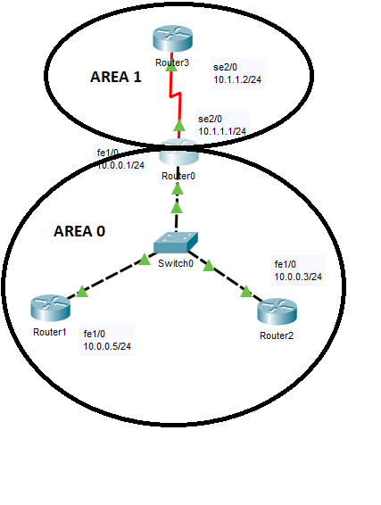
And that is all there is to implement multiarea OSPF (in this case the below areas have been set up and Router 0 has been configured as the ABR. The different interfaces on the Router have been assigned to different areas.
We can confirm that it’s got the Route from a different area by checking the route with the command show ip route:
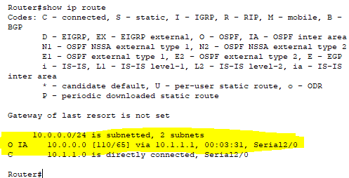
The IA (Inter-Area) part of this output is what shows us that this route is from another area. We can also see that it’s part of a /24 subnet.