GRE stands for Generic Routing Encapsulation. It is what is used to establish a tunnel between locations. It does this by creating a ‘second layer’ of IP addressing, encapsulating the first (private) IP address inside another packet.
How to configure a GRE tunnel
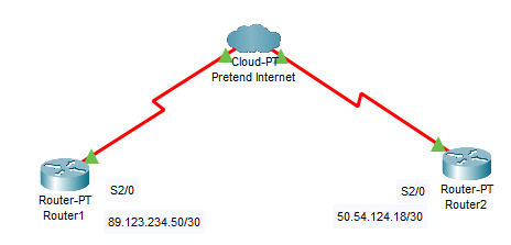
Again, packet tracer doesn’t have the facility to create tunnels built in. So unfortunately we are just going to have to write out the commands. I did however put up a dummy model together so you can see how it’s connected:
So on Router1 you begin by running the interface tunnel [INTERFACE NUMBER] command. – This creates a virtual interface, if you do a show interface brief command you can see that it is in there as ‘tunnel1’.
You then give that interface a local IP address, and on the other side you’ll need to repeat and give it another IP address in the same range.
Next up is the connection command tunnel mode gre ip. (there are lots of tunnel options available, but we are just going to look at gre and ip).
Then you put in the tunnel source (The public IP address that the connection will be coming from, pretty random in this one but you’d know it in a real life scenario). Then you put in the tunnel destination, again you’ll know this in a real life scenario.
Router1
interface tunnel 0
ip address 10.1.1.1 255.255.255.0
tunnel mode gre ip
tunnel source 89.123.234.50
tunnel destination 50.54.124.18
Router2
interface tunnel 0
ip address 10.1.1.2 255.255.255.0
tunnel mode gre ip
tunnel source 50.54.124.18
tunnel destination 89.123.234.50
Once these are both configured the tunnel state will change to up, and the private interfaces in the 10.1.1.0/24 range on both sides will be pingable.
In a real world scenario you would then implement routing to make sure the required private addresses are also accessible on other local networks on both sides.